Emily Lakdawalla • Jul 10, 2008
More things to see in the amazing HiRISE image of Phoenix' descent
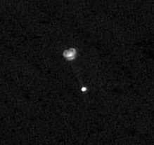
I have posted several times about the amazing photo captured by Mars Reconnaissance Orbiter's spy camera in space, HiRISE, of Phoenix under its parachute as it descended. There have been two common questions I've received about the photo: was there any color data taken, and what more can I tell you about how hard it was to take the photo? I've got answers to both questions for you today.
The HiRISE team has released a new version of this image, which includes some color data, though unfortunately not over Phoenix itself. HiRISE takes images in long, skinny strips, and only the very skinniest center portion of the strip ever contains any color data. Here's what the new color image looks like:

Before I get in to more detail about this image, I'll mention that the HiRISE team has confirmed what many people suspected: the sharp-edged, black dot located downrange of Phoenix and its parachute is the heat shield, falling toward the landing site on a trajectory similar to but slightly different from Phoenix's.

Okay, now for more information on taking the photo. The following discussion is possible because of a lot of help I received from one Timothy Reed, who was the Lead Optical Integration Engineer on HiRISE (he said he personally aligned all the optical and optomechanical components in the instrument. Strong work, Timothy!).
HiRISE was designed to take photos staring approximately straight down from the position of Mars Reconnaissance Orbiter, which is in a nearly circular orbit about 300 kilometers above the ground. Like many space cameras, HiRISE is a "pushbroom" style camera, which is different from a "framing" camera. The digital camera you may have at home is a framing camera: point, click, and one moment in time is captured on a two-dimensional detector array, usually a rectangular array measuring a few thousand pixels in each direction.
Pushbroom cameras are different. They have long, skinny detector arrays. The arrays are oriented perpendicular to the spacecraft's direction of motion. At an instant in time, the detector array picks up one line of pixels. When the spacecraft has advanced in its orbit by the distance corresponding to the height of one pixel, the detector picks up the next line. On earth, many photocopiers and scanners operate the same way. When that line of light goes across the glass platen, it's illuminating one linear section of your document and copying it.
Pushbroom cameras allow you to capture images of fixed width (as wide as your detector array) but of arbitrary length (usually limited only by something within the spacecraft's brain, its operating system or memory volume or whatever), making a pushbroom imager the camera style of choice if the goal is to acquire very large images, like if you're trying to map a whole planet. They work great as long as what you are imaging doesn't change with time, because each line of pixels is captured at a very slightly different time. (In the photocopier analogy, you need to hold still a book that you're photocopying, or the pages get smeared and illegible.) Mars' surface doesn't change very rapidly (except when there are active landslides or dust devils or moon shadows), so ordinarily the HiRISE team doesn't need to worry about things moving across their field of view.
But Phoenix wasmoving, and it was moving in not quite the same direction that the surface of Mars appeared to be moving. The point of the image was to capture a view of Phoenix, so the Mars Reconnaissance Orbiter team set up a slew -- a rotation of the spacecraft -- that was precisely timed to compensate for the motion of Phoenix. As the orbiter traveled along in its orbit and Phoenix fell to the ground the spacecraft rotated in such a way that, from the camera's point of view, Phoenix appeared to travel perpendicular to the orientation of the HiRISE detectors -- that is, it made the image of Phoenix build up in a way that was the way the HiRISE team designed their camera to capture images. So they got a really nice image of the lander. However, when they followed Phoenix, they allowed the ground to drift at an angle across the CCDs. Here's a cartoon Timothy sent me that shows what I'm talking about:

All right. Now, to understand why there would be gaps in the color channels (and, as it turns out, in some other places in the image as well), you need to know a couple more peculiarities about HiRISE. HiRISE isn't just one pushbroom imager. To build up images that are 20,000-plus pixels wide, it had to be built with ten detectors all lined up next to each other, each detector being 2,048 pixels wide. (Computer people like to build things in dimensions that are powers of 2.) To make sure the ten separate strips would blend together into a seamless image, they wanted to overlap the detectors at their ends. But if they're overlapped at the ends, that means that they needed to be staggered a bit on the detector plane. This probably isn't too clear as I'm writing it, but it should be much clearer when you see a photo of the detector plane, which Timothy sent me:

At this point in the HiRISE assembly the detector elements are bare but are correctly aligned, set to the same height, and measured so that the locations of the pixels is known to an accuracy of a few microns. Later a metal cover was installed that had spectral filters, sharp-edged rectangular apertures, and stray light baffling.Image: NASA / JPL-Caltech / UA / courtesy of Timothy Reed
At this point in the HiRISE assembly the detector elements are bare but are correctly aligned, set to the same height, and measured so that the locations of the pixels is known to an accuracy of a few microns. Later a metal cover was installed that had spectral filters, sharp-edged rectangular apertures, and stray light baffling.Each of those black rectangles is one 2,048-pixel-wide detector. If you've got a good head for geometry you may already have realized why there might be gaps in the image HiRISE took of Phoenix descending, particularly in the color channels. Because the detectors are staggered, with Mars traveling at an angle across the HiRISE focal plane, there are bits of Mars that just wiggle between the ends of two adjacent detectors. Here's another cartoon, showing the approximate geometry.

Key: Black rectangles show approximate locations of HiRISE chip assembly active areas overlaid onto a photo of the central group of six chips. Purple lines show where the angle of the ground image travel across the focal plane causes a gap in the overlap for the red (monochromatic) channel. Red lines show where the angle of the ground image travel across the focal plane causes a larger than normal overlap for the red channel. Green lines indicate the boundaries within which color data is available, where portions of image swaths reach all three color channels.
This is a fascinating story showing how necessary it sometimes is to have a deep understanding of an instrument in order to understand the data that comes from it. Space images are deceptive, because we tend to think they're like snapshots from the kind of cameras we have at home. Okay, maybe the cameras in space are radiation-hardened and able to deal with heavy jolts and low temperatures, but apart from that, how different can they be, right? The answer is that they can be very different, so it can be dangerous to read too much into space images until you have studied how the cameras really work.
All of this developed after my initial conversation with Timothy, in which I asked him to explain another detail about HiRISE, the fact that it uses Time-Delay Integration to build up its images. Time-Delay Integration is an important feature of many (in fact, most) pushbroom cameras in space, including not just Mars cameras but also the MVIC instrument on New Horizons, but until Timothy explained it to me I could not make myself understand what it was. Below is Timothy's explanation, which cleared things up for me -- I hope it helps you as well.
Time-Delay Integration Tutorial
by Timothy Reed
In the simplest kind of pushbroom imager, the ground is imaged onto a CCD array that is, say, 1,024 x 1 pixel. The array is oriented perpendicular to the direction of travel of the spacecraft. Each time that the spacecraft travels a distance that moves the image by one pixel height, that line is read out of the CCD. (In reality, you dump all the charge from each pixel into a serial readout register, and that register is busy reading out the previous line of data during the time that the next pixel height's worth of charge is accumulating in the CCD pixels. Otherwise you'd miss a portion of the line while you were reading it out.) Stack all the lines up, and you get an image.
Now, there are some limitations to this arrangement. You have to make sure that you can read out the entire length of the array in that one-pixel-height's-worth of time. If you make the array wider to cover a wider swath, you have to read out the register quicker. That, and the inability to reliably manufacture a very long array, puts a practical limit on the width of a detector element. So, it's usually broken up into multiple detector elements. More on that later.
In addition, with only a single pixel to collect photons for that very short amount of time, there's two serious limits on the sensitivity: dynamic range and signal-to-noise ratio of the image. Zipping past the ground in a few tens of microseconds can leave the image starved for light, especially in low illumination situations. The solution? Put a second row of pixels below the first. Now you have a 1,024 x 2 array. When the spacecraft travels one pixel height's worth, rather than dumping the accumulated charge into a register, you dump it "down the column" into another row of pixels where it accumulates more charge. When the accumulated charge is now read out, there's twice as much charge as you'd have gotten from the single-pixel-high array.
You do have to make sure that you've got the time interval matched correctly to the spacecraft velocity. Otherwise the sum of the charge in a particular column's readout will be from two different spots along the ground track, and you'll get smearing in that direction.
Now, the magic occurs! Add more rows to your heart's content. At each moment in time, each row contains the integrated charge of all the previous rows looking at one single line on the ground. (Hence, time-delay integration.) And the charge moves from row to row at the same rate that the image moves across the array.
Add 100 rows. Voila! Your signal is increased by 100 without having to increase the diameter of your telescope by a factor of 10.
The more rows you add, the more you have to be careful to get the timing correct, but the timing is basically just dependent on the spacecraft velocity (which is known and unchanging) and altitude (which changes, but is known for any image).
You now have a very flexible tool. You can integrate over all the pixels in a column to get maximum sensitivity. You can control the exposure of bright images by only accumulating charge over some of the pixels. You can "bin" the charge both in the across-track direction (adjacent pixels) and the along-track direction (adjacent TDI lines) to get less noisy, lower-resolution images.
HiRISE has 128 TDI lines, giving it wonderful sensitivity and dynamic range. But to take advantage of the potential gains, care had to be taken. If a point in the image starts at the top of a TDI column, and by the time it gets to the bottom row it has drifted into the adjacent column, the lateral resolution is compromised. That can happen if the spacecraft's roll around HiRISE's optical axis is incorrect by more than 1 milliradian. If the spacecraft jitters [such as when another instrument, like Mars Climate Sounder is moving], the image smears. If HiRISE is trying to capture a moving object like Phoenix, and the orientation of the spacecraft isn't lined up with the direction of motion, the image smears.
Back to segmented detectors. HiRISE has 14 individual 2,048 x 128 detector elements. Ten of them are lined up in a staggered array, overlapping by 48 pixels to create (effectively) a 20,000 pixel wide array. The individual detector outputs are stitched together to give the full width. Two additional pairs of detectors are stacked vertically above and below the center detectors -- these have infrared and blue-green filters to allow the center swath to collect full-resolution, panchromatic images.
A neat detail that not many people know: one would assume that during the construction of the detector array, the individual elements were precisely lined up absolutely parallel and perpendicular so that the TDI columns would all line up. (As noted before, anything that causes a point on the image to cross into another column smears the image.) Well, the optical system had a small amount of distortion, so the edges of the image didn't run straight down, they curved a slight amount. So each of the detector elements was tilted slightly to follow a gentle "smile" so that the performance at the edge of the field would be maximized. Had that not occurred, the edges of HiRISE images would be blurry.
Another reason for using segmented detectors...one or more elements can die or degrade, and the imager can still function, albeit with gaps in the data.
Back to Emily here: With this explanation, I now understand why the image of Phoenix under its parachute (below) looks so much sharper and clearer than the background. They oriented HiRISE so that Phoenix' motion was perpendicular to the HiRISE detector arrays, parallel to the time-delay integration columns. So they accumulated lots and lots of signal on Phoenix in the orientation that was correct to make the image really detailed and really sharp using the TDI technique. However, the ground was drifting across the TDI columns, so it smeared. To prevent that smear, they have to use a very small number of the TDI elements for the image, maybe four or eight -- which makes the image look more noisy -- and they have to reduce the resolution of the published image. They said as much in their original image caption, but because I didn't understand the TDI thing I didn't get what they were talking about.
Now I get it! And I hope that the ten of you readers who followed this entry this far get it too. You deserve a cookie.

Support our core enterprises
Your support powers our mission to explore worlds, find life, and defend Earth. You make all the difference when you make a gift. Give today!
Donate

 Explore Worlds
 Find Life
 Defend Earth

