Kevin Gill • Jan 25, 2017
Need a break from Earth? Go stand on Mars with these lovely landscapes
We have two rovers on Mars: Curiosity and Opportunity, which are our only current means of acquiring on-the-ground imagery of the planet’s surface. As beautiful and awe-inspiring as these pictures are, they are limited to where the rovers go.
Take this panorama, for instance, imaged by the Opportunity rover back in 2010:

Using images like this as both benchmarks and inspiration, I use real spacecraft data to approximate ground-level views of other places on Mars.
To do this, I work with two forms of data: Digital Terrain Models (DTMs) and satellite imagery. Simulating a camera on the ground requires very high resolution data, on the order of one or two meters per pixel. The best source for this data comes from HiRISE, the High Resolution Imaging Science Experiment, which is essentially a telescopic camera aboard the Mars Reconnaissance Orbiter. HiRISE is operated for NASA by the Lunar and Planetary Laboratory at the University of Arizona.
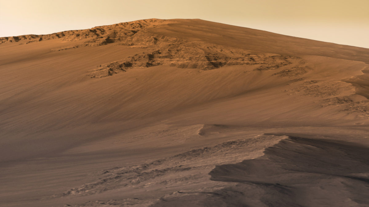
Here’s just one example of HiRISE data turned into a landscape:

The HiRISE folks create DTMs using data from two or more passes of their camera over the same target. By taking into account the difference in viewing angles, and with the help of some serious computing power, the team generates three-dimensional models with very high accuracy and only a small amount of uncertainty.
The altimetry—essentially, the height component—is provided by the DTM, while the texture is provided by the images themselves, called orthoimagery. Unfortunately, the color swaths of each dataset are too narrow to use in landscape modeling, so only grayscale images from HiRISE’s context camera are used.
When looking for a region to model, I take the following into consideration:
1. Is the data of sufficiently high resolution?
2. Is the data of sufficiently high quality (lacking seams, obvious polygons, etc.)?
3. Are there geological features on which I can focus?
4. Is the data wide enough to provide a sufficient angle of view?
5. Does the data provide, or can I fake, a realistic horizon?
6. Will the resulting image be interesting?
The first two considerations make sure the image will look good without obvious pixilation or other artifacts, since I am attempting to make the model look as realistic as possible. If the resolution is too low, the model will look blocky or cartoony.
The other considerations make sure the image is worth working on in the first place. Datasets that are very long and narrow force me to use a very narrow angle of view from the camera and won’t capture enough scenery. In terms of features in the data, I find it difficult to make flat plains interesting, and random bumps are confusing. On the other hand, I love high ridges with rocky outcrops, and craters with ripples at the bottom. If the camera angle includes some sky, I need to create a distant horizon. When evaluating a dataset, I can determine if it provides a horizon itself or if I will be able to fake one.

Once I have selected a dataset to work with, I download the highest resolution DTM and imagery data available. The orthoimagery data is formatted as a JPEG2000 file with project-specific extensions, which means it won’t work in gdal, ImageMagick, and rarely in Photoshop without plugins. The easiest method to work with it is by downloading HiView, the HiRISE team’s custom JPEG2000 viewing tool, and using it to convert the image into a TIFF file. If the image resolution is too high, HiView won’t export at the full size. This is okay, since I need a resolution that I can easily divide into chunks less than 8192 pixels per side (a limitation of my graphics card when rendering) that won’t require too much memory when rendering.
I do the chunking of the HiView TIFF file with ImageMagick, using the convert+crop+repage command. The DTM comes in a IMG format which gdal can handle, so I run gdalinfo to get the data min/max, then convert it into an unsigned 16-bit GeoTIFF, scaling that min/max between 0 and 65,535. I run the ImageMagick convert command on that to split it up, but adding a depth option to maintain the 16-bit values. The 16-bit TIFF is important: If you only use 8 bit (default) then you’re binning into 255 possible values leading to a very terraced and fake-looking model, which I’ve noticed is a common mistake made by people modeling terrains.
Also, the number of tiles made from the DTM data need to match the number made from the orthoimagery; this is a reason why I need to split the input data into chunks smaller than 8192. Again, that’s the limit of what my renderer and graphics card will allow me to use. This would be quite limiting if it were not for UV tiling in Maya.
When I create the scene in Maya, all I’m really making is one long polygon plane mesh with dimensions that match that of the data. I generally use 128x128 polygon subdivisions. Then it’s really just a matter of setting up a material for the mesh. I render using Mental Ray in Maya, so I use mia_material_x_passes with the Matte Finish preset. I bind the orthoimagery to the diffuse input and the DTM data to the displacement input and set up the UV mapping. I run a test render and make sure it works. If it does, I can go and tweak the displacement scale, which I tend to exaggerate to bring out detail.
Once a good camera angle is found, I’ll boost the mesh’s render subdivisions to 4, initial sample rate to 32, and extra sample rate to 24.

At this point, the rendered image is only grayscale. Enter Photoshop. I have a Photoshop file I keep using that has a series of color adjustments inspired by images returned from Curiosity and Opportunity. A default sky is provided by a Curiosity MastCam image. A gradient overlay provides some atmospheric scattering, and tilt-shift blur adds focus effects. Some hue/saturation and brightness levels tweaks later, we have a final image.
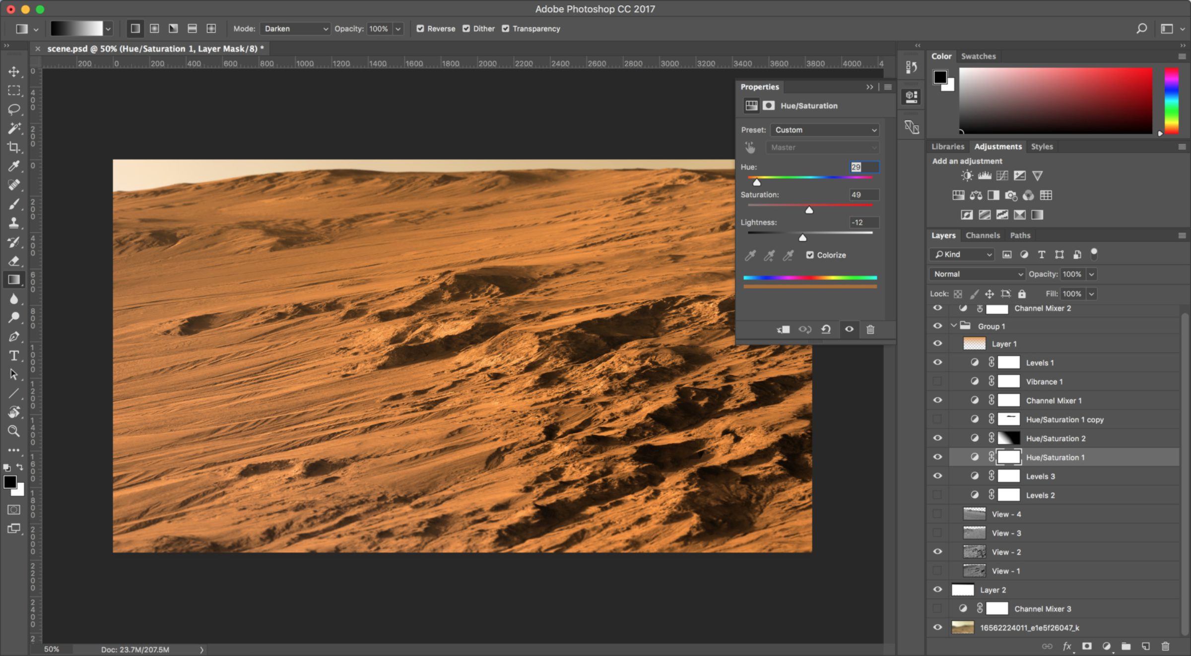
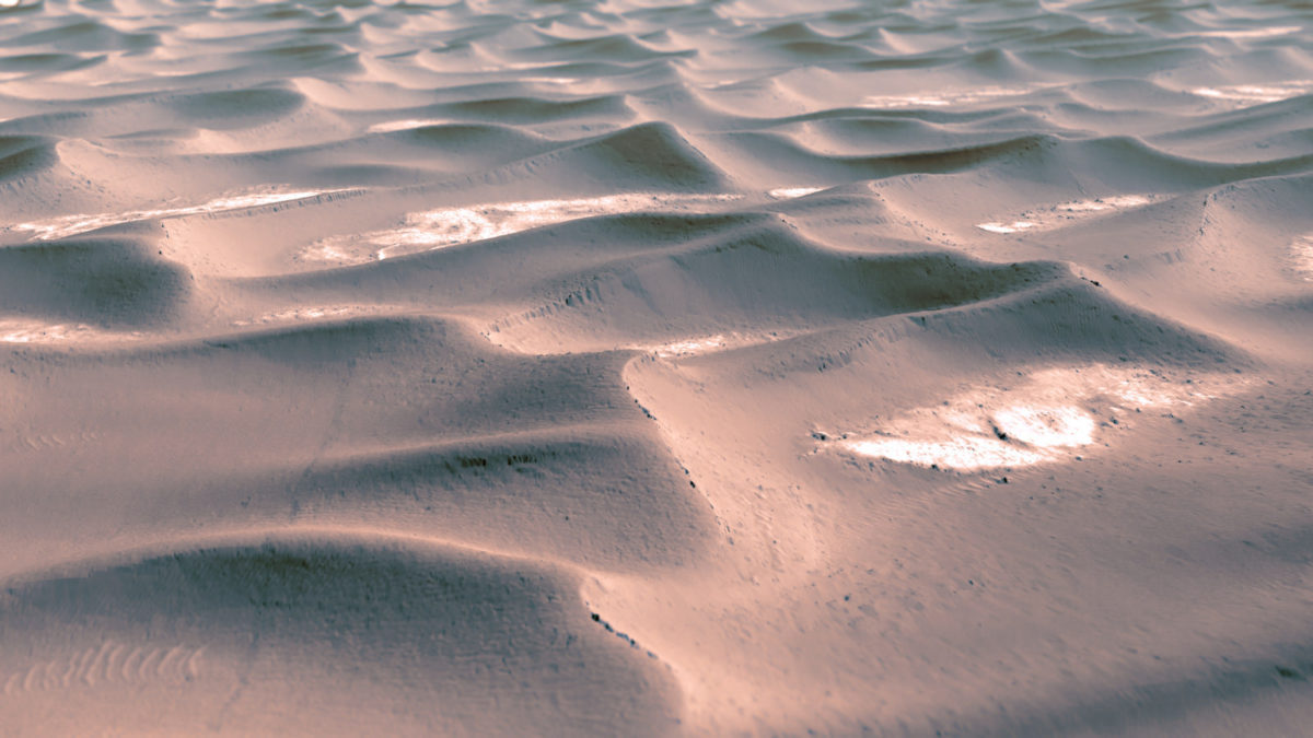
Here are some more examples of the results. You can also view all of my images on Flickr.




Support our core enterprises
Your support powers our mission to explore worlds, find life, and defend Earth. You make all the difference when you make a gift. Give today!
Donate

 Explore Worlds
 Find Life
 Defend Earth