Ian Regan • Jul 07, 2015
Saturn in Widescreen: The Voyager 2 Approach Movie
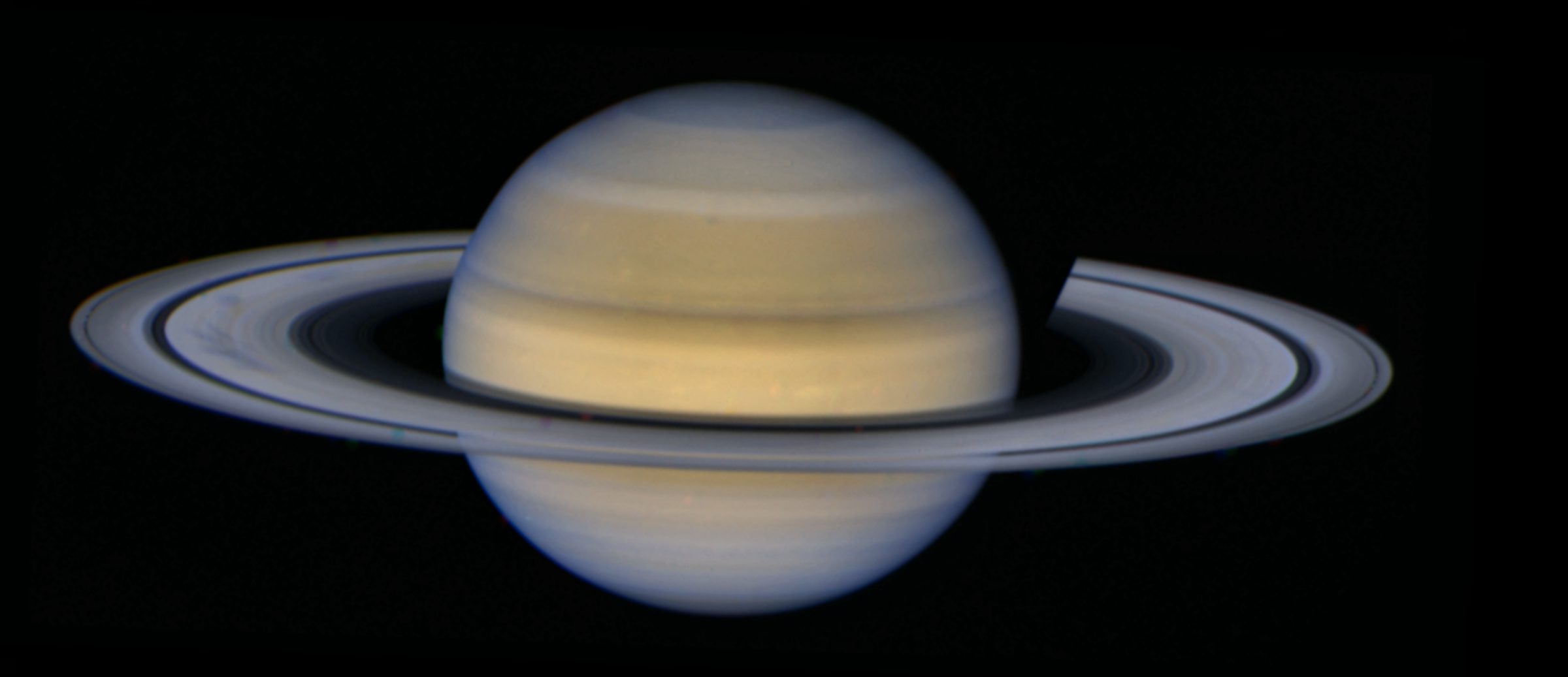
Voyager 2 captured this mesmerizing animated sequence over a 34-hour period in August 1981, as the spacecraft bore down on the ringed behemoth. A total of 600 clear-filtered frames, shuttered through Voyager’s narrow angle camera (NAC), were combined to produce 150 four-frame mosaics, covering the Saturnian system from ring tip to ring tip. The middle portion of Saturn's disc was intentionally omitted by Voyager mission planners to ensure the rings would be captured in their entirety.
Saturn and its Rings in Widescreen
This video comprises 600 photos taken by the Voyager 2 space probe as it bore down on the ringed planet in August 1981. Each frame of the film is actually a mosaic of 4 clear-filtered narrow angle camera (NAC) images. The color comes from a separate Orange-Green-Ultraviolet composite taken by Voyager some time prior to this sequence.
A variety of moons and ring spokes can be seen in motion as the film progresses, and it is notable that the spokes appear darker on the left ansa (this may be due to the phase angle). The middle portion of Saturn's disc was intentionally omitted by Voyager to ensure the rings were captured in their entirety in each 4-frame mosaic.
Video: NASA / JPL-Caltech / Ian ReganThis extended observation started on August 13th at 11:18 UTC, ending 34 hours later at 21:15 UTC the following day. Tasked with following up Voyager 1's rather unexpected discovery of transient spoke-like features in the rings, Voyager 2 was in prime position to investigate these shadowy apparitions further.
A variety of moons (at least seven) and ring spokes sweep around the planet as the film progresses, and it is notable that the spokes appear darker against the left ring (or 'ansa'); this may be due to the subtle difference in phase angle: put simply, the left ansa is seen at slightly more of a perpendicular angle to the incident sunlight than the right ansa.
The color comes from a separate composite taken with Voyager's NAC some time prior to this sequence, and approximates natural color with images recorded through Orange, Green and Ultraviolet filters.
How It Was Done
Having chanced upon the existence of these images, I decided to experiment with the data, starting with the download of the geometrically corrected and calibrated image files using the OPUS PDS tool. These images have gone through a systematic process of dark current removal and flat-fielding, in addition to the removal of the distortions and reseaux marks commensurate with Voyager’s antiquated TV camera system. After using Björn Jónsson’s excellent IMG2PNG utility to convert the native IMG files to a more convenient and friendly PNG format, the images were ready to be processed.
More talented and ingenious image processors than myself might have made use of something known as the SPICE kernel dataset to determine the exact attitude and orientation of Voyager’s scan platform, thereby pinning down the exact position of Saturn within each frame. Alas, this approach lies beyond my abilities as a semi-casual image processor! So, reverting to techniques within my comfort zone, I broke down the problem of accurately compositing 150 mosaics of Saturn and its rings.
The first issue was the lack of overlap: the frames were taken with sufficient margin of error to ensure that each side or ‘ansa’ of the rings would be captured in its entirety with just two consecutive photos—a conservative approach that meant the center of Saturn’s disc was usually omitted. This made the mosaicing process more complicated, and necessitated a methodical approach to take account of the increasing angular size of the planet during the 34-hour period (an increase of approximately 12%, in fact).
The images in each 4-frame mosaic were more or less centered on the following feature in the Saturn system: LEFT ANSA, LEFT LIMB, RIGHT TERMINATOR, RIGHT ANSA. Areas covered by multiple images are commonly known as 'footprints'. I decided that before I should tackle the job of assembling mosaics, first I needed to carefully align and stabilize all the images taken by Voyager in each of the aforementioned footprints.
Starting with all 150 frames containing the LEFT ANSA, I aligned the images using a high-contrast feature: in this case, the bright outer edge of the A-ring. I decided, rather arbitrarily, to make sure that this tip should be 150 pixels from the left edge of the image frame. Vertically, the ansa should be centered in the frame.
Okay then! The question now was: how do I automatically shift each frame so that the rings end up where I want them to be? The solution was to record and modify a bespoke Python script macro inside Corel Paint Shop Pro X6. The scripts would measure the exact position of the rings, and then apply corrections in both the 'x' and 'y' dimensions accordingly. Here is but one example:
if (frame[i]=="C4362618_GEOMED.png") {moveX = 5.0; moveY = 2.5;}
The result of aligning all frames within the LEFT ANSA footprint:
I repeated the same process for the frames in the other three ‘footprints’, using whichever feature was most suitable for alignment purposes. Hoping to achieve sub-pixel precision, the measurements were made on images at a scale of 200%, then applied using a separate macro within the ImageJ software utility.
Images damaged by cosmic ray hits, missing lines or truncated sections, and other flaws riddling the Voyager dataset complicated the process massively. Repairing these issues ate up a significant percentage of the total time and work invested in the project. The screenshot of the OPUS PDS results page shows some of the damaged frames that needed extensive processing, or replacing altogether.
The Mosaicing Stage
Once I aligned all the frames within the four footprints covering the Saturn system, I assembled the 150 mosaics in order to produce the final animated sequence. For reasons both of time and accuracy, I preferred a semi-automated process, especially since the steadily increasing angular size of Saturn added yet another level of complexity.
Thus, I resolved to construct the first mosaic manually, which would be my reference for the remaining 149 mosaics in the movie. I measured the ratios of pixel distances between major features, such as the Maxwell Gap within the C-ring, the inner edges of the C-ring, the outer edges of the A-ring, and the extent between the limb on the left side, and the terminator on the right.
Having measured these key points, I used the information to manually construct mosaics for frames No.50, No.100, and No.150. Since the increase in the apparent size of Saturn is non-linear (due to the acceleration of the spacecraft toward the planet), I resorted to using ‘cubic splines’ plotted in a spreadsheet to give smoothly interpolated values for the expected pixel locations of these features in the other frames.
After the values in this spreadsheet were 'plugged-in' to Paint Shop Pro macros, each mosaic was built up in a progressive manner, first joining the two frames on one side of the planet (specifically the LEFT ANSA and LEFT LIMB footprints), then likewise for the other two frames, before joining the two separate mini-mosaics to form the completed 4-image frame.
Rinse and repeat another 149 times!
Adding Color
Once completed, the black and white movie sequence looked magnificent. However, Voyager 2 had shuttered an orange-green-ultraviolet color composite only a matter of hours prior to this ring movie. Although vastly lower in resolution, it was suitable for colorizing these 4 frame mosaics. The prospect of aligning and resizing the color frame to the black and white mosaics was a non-trivial problem. Once again, I chose to manually work on four keyframes, overlaying the color data on the B&W mosaics, then utilizing the Excel cubic splines macro to plot values for all other frames.
This example line of code tells Paint Shop Pro how to distort the color overlay to fit the black and white data for one frame, with x and y values calculated for the distortion grid:
‘C4362822_GEOMED': H1X = -4.5': H1Y = 1409.07;': H2X = -4.40;': H2Y = -4.62;': H3X = 3259.09;': H3Y = -8.38;': H4X = 3259;': H4Y = 1405.32;
I then turned the finished frames into an AVI file using VirtualDub, and finally converted to MP4 format with Serif MoviePlus, before uploading to both the YouTube and Vimeo video sharing platforms.
Epilogue
So, you might wonder, why hasn't this vintage observation not seen the light of day until now? The answer is, it has! But sadly only in this heavily cropped and panned-and-scanned presentation:
And there we have the crux, gentle reader: vintage data processed with modern technology and techniques, many of which are in the realm of the average home computer owner, can be made to sparkle again. What other treasures lurk, as yet unseen, within the old datasets radioed back to Earth by the Voyagers and their contemporaries? To find out, stay tuned to these very pages...
Software Used:
- Microsoft Excel (with third-party cubic spline macro)
- Corel Paint Shop Pro x6 (16-bit image processing suite with Python scripting capabilities)
- ImageJ (Java based image processing application, ostensibly for medical analyses, but is useful for other work, given its extremely powerful macro capabilities and ability to process images in 32-bit mode).
- VirtualDub (freeware video compiler and editor)
- Serif MovePlus (semi-professional movie editing suite)
Support our core enterprises
Your support powers our mission to explore worlds, find life, and defend Earth. You make all the difference when you make a gift. Give today!
Donate

 Explore Worlds
 Find Life
 Defend Earth


